
hydraulic schematic diagrams of mill plant fabricante Agarrando fuerte capacidad de producción, fuerza de investigación avanzada y excelente servicio, Shanghai hydraulic schematic diagrams of mill plant proveedor crea el valor y aporta valores a todos los clientes.
 WhatsApp)WhatsApp)
TS 112 - Process and Instrumentation Diagrams (P&ID) SA Water - Technical Standard Revision 2.0 - 16 December 2015 Page 8 of 27 For Official Use Only Uncontrolled When Printed Or Downloaded 2 Scope This Technical Standard (TS) shall apply to all the Process / Piping and Instrumentation Diagrams

To help with commercial heating system design, Hamworthy provide hydraulic schematic drawings.View and download pre-defined hydraulic schematics for condensing boiler systems. There are hydraulic schematic drawings listed for most of our products...
Hydraulic Schematic Diagrams Of Mill Plant Machine. Schematic diagram for pcb crusher machine schematic diagram of crusher plant, and it is an integrated work team with two mobile crushers mobile jaw crusher and mobile cone crusher cone crusher diagram ciriorgin mineral processing ball mill flow diagram cone crusher diagram,cone wiring diagrams ...
Mar 07, 2015· determine vertical hydraulic Figure 1: Schematic diagram of the proposed field permeameter. companying drawings wherein: Fig. 1 is a schematic diagram of a complete hydraulic press or system for carrying out the present process, and for operating. vertical roller press raw mill flow diagram Grinding Mill. Cement hydraulic circuit diagram for
Hydraulics Systems Diagrams and Formulas for a front end loader, winch, logsplitter, and other useful formulas ... The diagram shows a winch powered by a hydraulic motor. The directional control valve with built-in relief features optional flow control to control the speed of the winch . The hydraulic pump and motor must be matched to the ...
Pulp and paper plant - pulp mill Explore equipment and application specific to your industry in the below schematic. You can click on red hotspots in the schematic or on items in the right-hand equipment menu to see corresponding lubricant information.
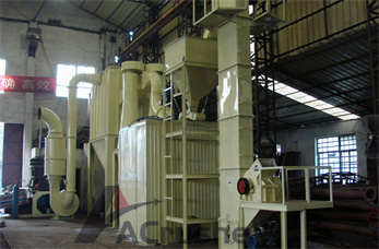
Figure 5-4 shows a typical hydraulic parallel system schematic. Any actuator in this circuit can move at any time and is capable of full force and speed when the pump produces sufficient flow. Parallel circuits that have actuators that move at the same time must include flow controls to keep all flow from going to the path of least resistance.
How a Wind Turbine Works. Learning how a wind turbine works is easy as long as you first make sure to know how a turbine generator works.. The diagram of the wind turbine above is a side view of a horizontal axis wind turbine with the turbine blades on the left.
diagrams for fluid power systems are Pictorial, Cutaway, and Graphic. These symbols are fully explained in the USA Standard Drafting Manual (Ref. 2). 1.1.1Pictorial symbols are very useful for showing the interconnection of components. They are difficult to standardize from a functional basis.
The previous article in this series introduced fluids (hydraulic and pneumatic) circuit elements. This article will describe three example hydraulic schematic diagrams. Hydraulic (oil under pressure) controls are used when very heavy components must be moved with accuracy and speed is .

Knowing how to wire a dump trailer remote can be a little confusing, but just relax, we are here to help! The first thing to consider: Are you wiring a Power-Up/Power-Down (Double-Acting) or Power-Up/Gravity-Down (Single-Acting) hydraulic pump.
Have you ever wondered how pressure energy is stored in hydraulic accumulators? Read here to learn about the working of hydraulic accumulators, the basic components of a hydraulic accumulator, and factors which limit the pressure inside the accumulator. Illustrations provided include the Kinetic Energy Recovery System or KERS system of race cars, cut-away drawings of some different styles of ...
A schematic illustrating the major components of a hydraulic disc brake system. A hydraulic brake is an arrangement of braking mechanism which uses brake fluid, typically containing glycol ethers or diethylene glycol, to transfer pressure from the controlling mechanism to the braking mechanism.
This schematic diagram must be properly understood. It is the basis upon which Hydro-electric power station designs are done. The individual power station complexity may differ slightly to the schematic and yet over and above that will use the same principle.

Hydraulic Piping Standard Handbook is intended for professionals working within industries where hydraulic piping is used. This Handbook offers relevant information in one package for anyone installing or using non-welded hydraulic piping systems. This Handbook gives easy-to-use guidelines and compiles all relevant information in one place
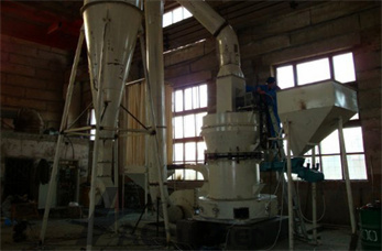
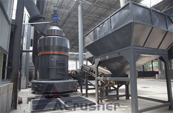
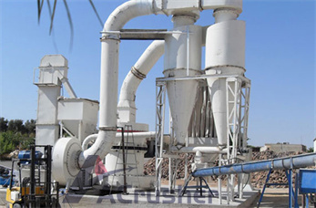
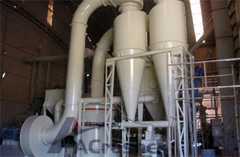
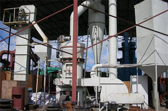
Hydraulic Schematic Diagrams Of Mill Plant. We are a large-scale manufacturer specializing in producing various mining machines including different types of sand and gravel equipment, milling equipment, mineral processing equipment and building materials equipment.
Have you ever wondered how hydroelectric power plants work to convert energy from water into electricity? This article goes over six important components of a hydroelectric power plant to give you a better understanding of how the potential energy of water can be used effectively.
Many of the major hydraulic components are not visible from a single vantage point and time can be lost simply in becoming familiar with the hydraulic system. This time is better spent reviewing the circuit diagram and relating the trouble symptoms to components which could be at fault.

Oct 21, 2017· Types Of Hydraulic Motors And Their Symbol Used in Hydraulic Circuit Diagram. 4. Hydraulic Cylinder. Hydraulic cylinder is a mechanical hydraulic actuator that converts hydraulic energy or hydraulic pressure into linear displacement. It .
Jul 30, 2019· This video is unavailable. Watch Queue Queue. Watch Queue Queue
For a pump storage power plant which was originally designed for classical pumped storage operation (i.e. pumping resp. power consumption during the night and power production resp. turbining during the daytime) extensive analysis on the suitability for the operational mode of hydraulic .

Power Plant Electrical Distribution Systems Gary W Castleberry, PE Course Description This one hour course provides an introduction to the design of electrical distribution systems found in electrical power generation plants. The type of equipment utilized .

hydraulic fracturing has serious environmental and water pollution related issues. Instrumentation Used to create/operate complex instruments in space rockets, gas turbines, nuclear power plants, industrial labs Jigs and fixtures Work holding devices, clamps, stoppers, indexers
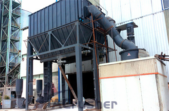
hydraulic schematic diagrams of mill plant – beltconveyers. schematic diagram of a rollermill – CGM Grinding Plant. Grinding Mills – Efficient crushing-type mills – T130X Superfine Mill – LM Vertical Roller Mill .» Free online chat! hydraulic schematic diagrams of mill plant – .